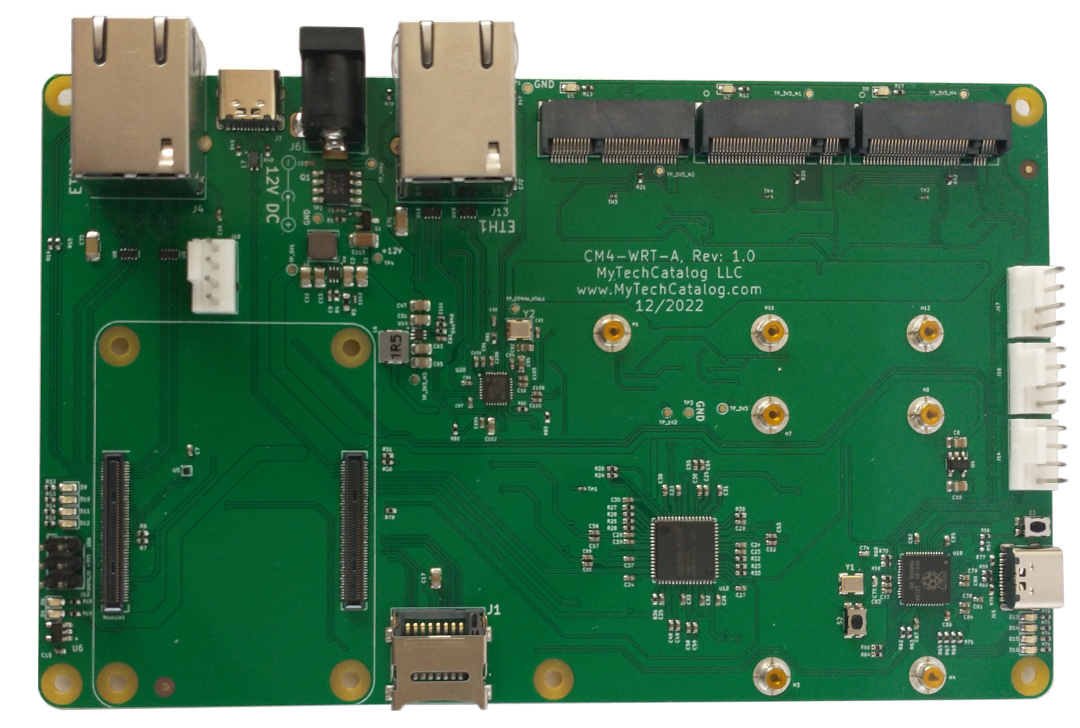
The CM4-WRT-A is a Raspberry Pi CM4 carrier board that can be used to create a gigabit router capable of supporting WiFi 6/6E as well as a 4G/5G backup connection. Currently sold on Tindie
Specifications
- Two PCIe M.2 Key M slots for NVME SSDs. Adapters will be made available soon (if the market does not currently offer any) to convert the middle slot into a M.2 Key B or Mini PCI-E (mPCIe) slot so as to support an optional 4G/5G modem for those who need one.
- One PCIe M.2 Key E connector for a WIFI 6/6E adapter.
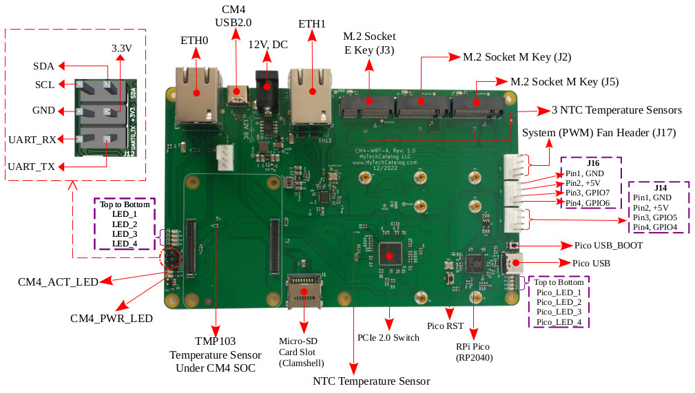
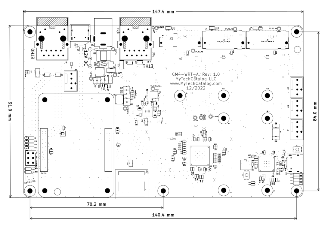
- Two 1GBit Ethernet connectors: ETH0 the default LAN interface, and ETH1 typically used as the WAN interface.
- 5V PWM fan connectors: J17 and J18 (next to the CM4). The other two connectors are reserved for special GPIO functions, such as CM4 reset switch and CM4 Boot to USB Mass Storage mode.
- One Raspberry Pi Pico RP2040 micro-controller performs PWM fan control, board temperature sensor monitoring and watchdog functions.
- A six-pin header (J12) provides access to the CM4's UART0 and I2C bus. An OLED screen can be connected to this header and mounted into an updated version of the case.
- One USB 2.0 port connected to the CM4, can be used in both device and host mode.
- One USB1.1 port connected the RPi Pico, can be used in both device and host mode.
- Power Input: 12V DC. A power supply with a 5.5 X 2.1mm female barrel connector (center positive) and enough power for all the attached peripherals (36W minimum). A good power supply with sufficient power is critical.
- Support for power switch to power down CM4, ETH1 and PCIe peripherals.
- Dimensions: 147.4 x 91.0 mm
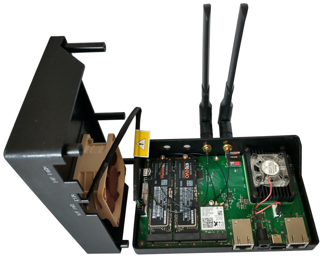
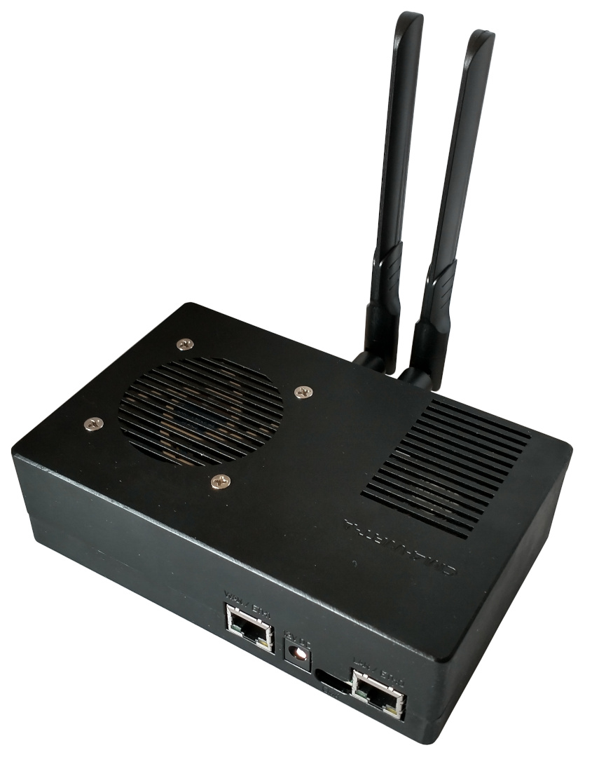
3D Printed Case (with a 60mm fan vent) for the CM4-WRT-A Baseboard
There is a 3D printed case available for the CM4-WRT-A baseboard. The files for which are available in the CM4-WRT-A GitHub repo
| CM4 | Pico | Notes |
|---|---|---|
| GPIO5 / RXD3 | GPIO0 / UART0 TX | |
| GPIO4 / TXD3 | GPIO1 / UART0 RX | |
| RUN_PG | GPIO16 | 10k pull down near Pico |
| nEXTRST | GPIO17 | |
| nRPIBOOT | GPIO18 | |
| Global_EN | GPIO19 | 10k pull down near Pico |
#Power Switch
The CM4-WRT-A baseboard supports a power switch via a jumper with reference J16. Connect a momentary switch
between pin 3 (GPIO7) and pin 1 (ground). If the service picod is
up and running on the CM4, a short button press, (longer than 0.25 seconds and less than 2 seconds) will cause
the service picod to issue a graceful shutdown command. RPi Pico will also power down ETH1, and the
PCIe peripherals. If the button is pressed for more than 2 seconds, the CM4 will be reset (hard reset) without a
chance to save settings or files. A hard reset should only be done as a last resort for an unresponsive RPi CM4.
When the CM4 is gracefully shutdown with a short press of the power button, it can be powered on again with another short button press.
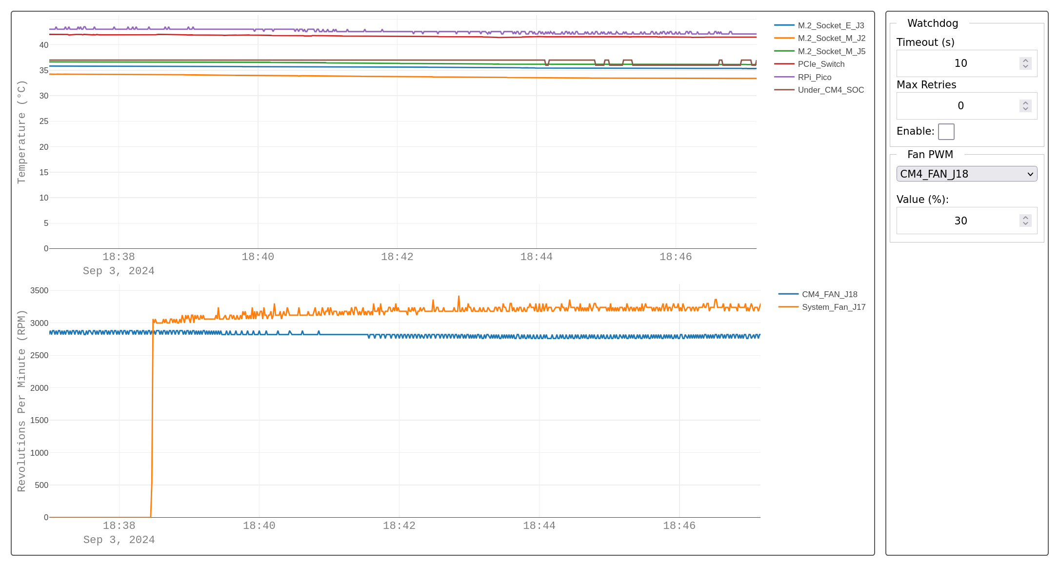
#Dashboard
When compiled for Raspbian, and other Debian variants, the CM4-WRT-A software consists of a service called picod, which communicates with the Raspberry Pi Pico collecting periodic measurements from six temperature sensors on the CM4-WRT-A board, as well as the system fan Revolutions Per Minute (RPM). Below is a screenshot showing an example of a built-in dashboard displaying the six temperature sensors, and system fan RPM of the CM4-WRT-A board.
The dashboard is available at http://localhost:8086/ by default. This location is not accessible from outside the RPi CM4 itself. As such, an SSH tunnel can be created with the following command to forward port 8086 to your localhost:
ssh -L 8086:localhost:8086 username@cm4_ip_addressThe picod service also natively supports InfluxDB. The network interface (such as localhost above) where the dashboard is accessible, can be configured via the picod config file located at /etc/picod/picod.conf on the CM4-WRT-A router.
Video
I have a video that goes over the setup procedure, or you can skip to the next article: